Where the EPNMRV 030 Is Used
Common installations include automated sliding door systems in commercial buildings, electronic component assembly lines, small screw conveyors for powder handling, label applicators, and rotary filling machines. In Australia, the EPNMRV 030 is widely used by packaging OEMs in Victoria and food equipment builders requiring a compact reducer for light mixer drives.
When to Choose This Model
The EPNMRV 030 is the correct choice for output torques up to approximately 22 Nm at continuous duty, where the application benefits from the 100:1 self-locking ratio range. For higher torque or larger IEC motor flanges (71B14+), consider the EPNMRV 040.
For detailed information on housing materials, worm gear efficiency characteristics, and installation orientation guidelines, refer to the EPNMRV Series overview.
EPNMRV 030 Specifications
All data for the EPNMRV 030 standalone gearbox. Input speed: 1,400 RPM.
Selection Table (Input: 1,400 RPM)
| Input Power (kW) | Ratio | Output Speed (RPM) | Torque (Nm) | Radial Load (N) | Service Factor fs |
|---|---|---|---|---|---|
| 0.06 | 7.5 | 187 | 3 | 683 | 7.0 |
| 10 | 140 | 3 | 752 | 5.4 | |
| 15 | 93 | 5 | 861 | 3.9 | |
| 20 | 70 | 6 | 948 | 3.1 | |
| 25 | 56 | 7 | 1021 | 3.1 | |
| 30 | 47 | 8 | 1085 | 2.5 | |
| 40 | 35 | 10 | 1194 | 1.9 | |
| 50 | 28 | 11 | 1286 | 1.5 | |
| 0.09 | 10 | 140 | 5 | 752 | 3.9 |
| 15 | 93 | 7 | 861 | 2.6 | |
| 20 | 70 | 9 | 948 | 2.1 | |
| 25 | 56 | 10 | 1021 | 2.1 | |
| 30 | 47 | 12 | 1085 | 1.7 | |
| 40 | 35 | 14 | 1194 | 1.2 | |
| 50 | 28 | 17 | 1286 | 1.0 | |
| 0.12 | 15 | 93 | 9 | 948 | 2.0 |
| 20 | 70 | 12 | 1021 | 1.6 | |
| 25 | 56 | 14 | 1085 | 1.6 | |
| 30 | 47 | 16 | 1194 | 1.3 | |
| 40 | 35 | 19 | 1286 | 0.9 | |
| 50 | 28 | 22 | 1367 | 0.8 | |
| 0.18 | 15 | 93 | 14 | 1447 | 1.3 |
| 20 | 70 | 17 | 1504 | 0.9 | |
| 25 | 56 | 21 | 1657 | 1.1 | |
| 30 | 47 | 24 | 1824 | 1.0 | |
| 40 | 35 | 29 | 1964 | 0.8 |
fs = Service Factor. Required minimums: A (uniform) fs >= 1.0 | B (moderate shock) fs >= 1.25 | C (heavy shock) fs >= 1.75. Contact our engineers for application-specific verification.
Gear Engagement Parameters
| Ratio (i) | Worm Starts (Z1) | Lead Angle | Module (m) | Dynamic Eff. | Static Eff. | Self-Locking |
|---|---|---|---|---|---|---|
| 7.5 | 4 | 20 deg 19 min | 1.5 | 0.87 | 0.85 | No |
| 10 | 4 | 15 deg 31 min | 1.5 | 0.82 | 0.77 | No |
| 15 | 2 | 10 deg 29 min | 1.5 | 0.77 | 0.73 | No |
| 20 | 2 | 5 deg 42 min | 1 | 0.73 | 0.68 | No |
| 25 | 1 | 6 deg 10 min | 1.75 | 0.68 | 0.65 | No |
| 30 | 1 | 5 deg 17 min | 1.5 | 0.65 | 0.59 | No |
| 40 | 1 | 3 deg 52 min | 1 | 0.59 | 0.55 | Marginal |
| 50 | 1 | 3 deg 26 min | 0.9 | 0.55 | 0.44 | Marginal |
| 60 | 1 | 2 deg 52 min | 0.75 | 0.50 | — | Yes (marginal) |
| 80 | 1 | — | — | — | — | Yes |
| 100 | 1 | — | — | — | — | Yes |
Self-locking should not be relied upon as the sole backstop — external brakes recommended for safety-critical loads.
Overall Dimensions (mm)
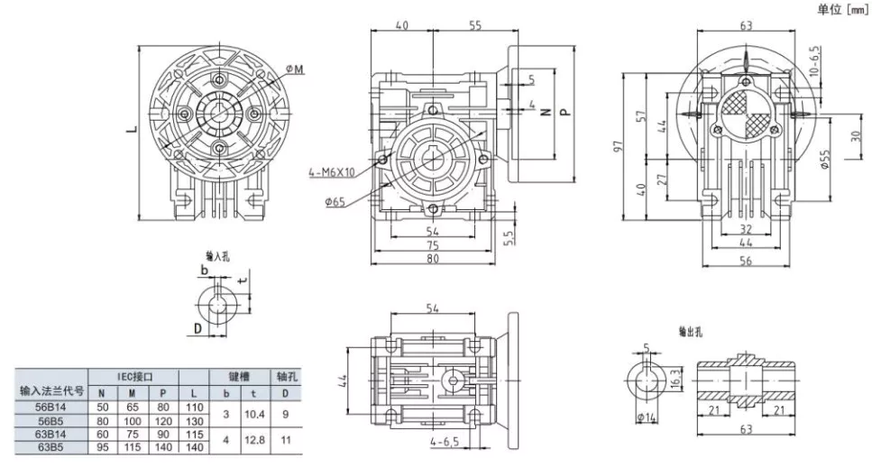
| Model | A | B | C | D(H8) | F | G | H | H1 | I | M |
|---|---|---|---|---|---|---|---|---|---|---|
| EPNMRV 030 | 80 | 97 | 20 | 54 | 10.4 | 9 | 32 | 56 | — | 27 |
All dimensions in mm. Default mounting: B3 (horizontal). Specify orientation at time of order.
Output Shaft Dimensions (mm)
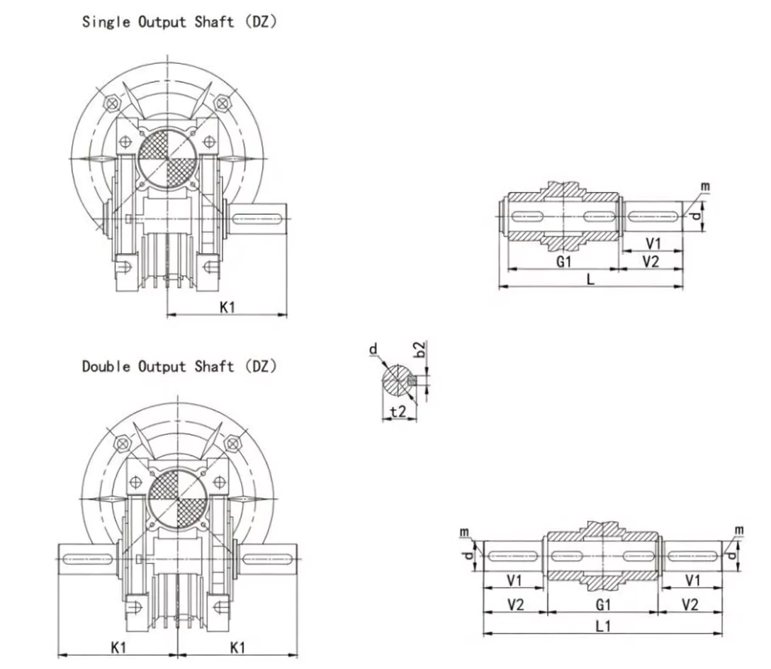
| Model | G1 | K1 | L | L1 | b2 | t2 | d(h6) | m | V1 | V2 |
|---|---|---|---|---|---|---|---|---|---|---|
| EPNMRV 030 | 63 | 64 | 102 | 128 | 5 | 16 | 14 | M6 | 30 | 32.5 |
d(h6) = output shaft diameter with h6 tolerance. Contact us for double-side output (SZ) or hollow shaft configurations.
Other Models in This Series
The EPNMRV range covers centre distances from 25 mm to 150 mm.