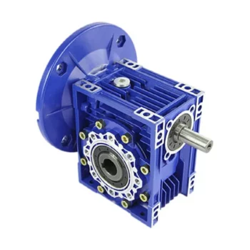
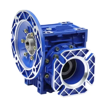
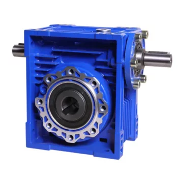
Product Description
High Rpm RV series Aluminum Alloy Worm Gear box NMRV 571-150 Reducer Variable Wheel Drive Speed Reduction Worm Gearbox
Product Parameters
Specification
|
Type |
Worm Gearbox/Worm Gear Speed Reducer |
|
Model |
NMRV:571,030,040,050,063,075,090,110,130,150 |
|
Center distance |
25-150mm |
|
Ratio |
5,7.5,10,15,20,25,30,40,50,60,80,100 |
|
Torque |
1.8-1800Nm |
|
Motor |
2 pole, 4 pole, 6 pole |
|
Mounting position |
Omnidirectional |
|
Color |
Blue/Silver grey Or On request |
|
Material |
NMRV571~090:Aluminum alloy; NMRV110~150 Cast iron |
Details
Multiple inputs and outputs
Feature
1. Mad of high-quality aluminum alloy,light weight and non-rusting
2. Large output torque
3. Smooth in running and low in noise,can work long time in dreadful conditions.
4. High in radiating efficiency.
5. Good-looking in appearance,durable in service life and small in volume.
6. Suitable for omnibearing installation.
contact-info.html
|
Model |
NMRV571, NMRV030, NMRV040, NMRV050, NMRV063, NMRV075, NMRV090, NMRV110, NMRV130, NMRV150 |
|
Ratio |
5,7.5,10,15,20,25,30,40,50,60,80,100 |
|
Output Torque |
1.8-1760Nm |
|
Application |
Machinery Industry |
|
Input Speed |
900-2800RPM |
|
Output Speed |
10-250RPM |
|
Material |
Housing: Size 25-110 Is Aluminum Alloy, Size 110-150 Is Cast-Iron |
|
Worm Wheel: ZCuSn10Pb1 |
|
|
Worm:20Cr |
|
|
Pinion:Tin Bronze |
|
|
Output Shaft: Steel-45# |
|
|
IEC Flange |
IEC Standard Flange Or On Customer Request |
Detailed Photos
/* January 22, 2571 19:08:37 */!function(){function s(e,r){var a,o={};try{e&&e.split(“,”).forEach(function(e,t){e&&(a=e.match(/(.*?):(.*)$/))&&1
| Hardness: | Hardened Tooth Surface |
|---|---|
| Installation: | 90 Degree |
| Layout: | Expansion |
| Gear Shape: | Bevel Gear |
| Step: | Single-Step |
| Type: | Gear Reducer |
| Samples: |
US$ 30/Piece
1 Piece(Min.Order) | |
|---|

Calculating Gear Ratio in a Worm Reducer
The gear ratio in a worm reducer is determined by the number of teeth on the worm wheel (also known as the worm gear) and the number of threads on the worm shaft. The gear ratio formula for a worm reducer is:
Gear Ratio = Number of Teeth on Worm Wheel / Number of Threads on Worm Shaft
For example, if the worm wheel has 60 teeth and the worm shaft has a single thread, the gear ratio would be 60:1.
It’s important to note that worm reducers have an inherent self-locking property due to the angle of the worm threads. As a result, the gear ratio also affects the mechanical advantage and the system’s ability to resist backdriving.
When calculating the gear ratio, ensure that the worm reducer is properly designed and that the gear ratio aligns with the desired mechanical characteristics for your application. Additionally, consider factors such as efficiency, load capacity, and speed limitations when selecting a gear ratio for a worm reducer.

How to Calculate the Input and Output Speeds of a Worm Gearbox?
Calculating the input and output speeds of a worm gearbox involves understanding the gear ratio and the principles of gear reduction. Here’s how you can calculate these speeds:
- Input Speed: The input speed (N1) is the speed of the driving gear, which is the worm gear in this case. It is usually provided by the manufacturer or can be measured directly.
- Output Speed: The output speed (N2) is the speed of the driven gear, which is the worm wheel. To calculate the output speed, use the formula:
N2 = N1 / (Z1 * i)
Where:
N2 = Output speed (rpm)
N1 = Input speed (rpm)
Z1 = Number of teeth on the worm gear
i = Gear ratio (ratio of the number of teeth on the worm gear to the number of threads on the worm)
It’s important to note that worm gearboxes are designed for gear reduction, which means that the output speed is lower than the input speed. Additionally, the efficiency of the gearbox, friction, and other factors can affect the actual output speed. Calculating the input and output speeds is crucial for understanding the performance and capabilities of the worm gearbox in a specific application.

What is a Worm Gearbox and How Does It Work?
A worm gearbox, also known as a worm gear reducer, is a mechanical device used to transmit rotational motion and torque between non-parallel shafts. It consists of a worm screw and a worm wheel, both of which have helical teeth. The worm screw resembles a threaded cylinder, while the worm wheel is a gear with teeth that mesh with the worm screw.
The working principle of a worm gearbox involves the interaction between the worm screw and the worm wheel. When the worm screw is rotated, its helical teeth engage with the teeth of the worm wheel. As the worm screw rotates, it translates the rotational motion into a perpendicular motion, causing the worm wheel to rotate. This perpendicular motion allows the worm gearbox to achieve a high gear reduction ratio, making it suitable for applications that require significant speed reduction.
One of the key features of a worm gearbox is its ability to provide a high gear reduction ratio in a compact design. However, due to the sliding nature of the meshing teeth, worm gearboxes may exhibit higher friction and lower efficiency compared to other types of gearboxes. Therefore, they are often used in applications where efficiency is not the primary concern but where high torque and speed reduction are essential, such as conveyor systems, elevators, automotive steering systems, and certain industrial machinery.


editor by CX 2024-03-14