Product Description
Technical Features
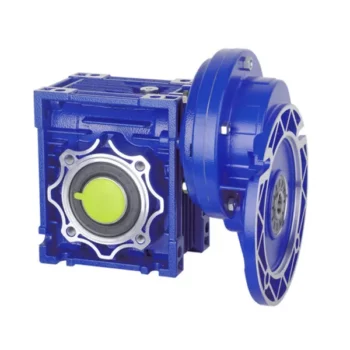
The high degree of modularity is a design feature of SRC helical gearboxes range. It can be connected respectively with motors such as normal motor, brake motor, explosion-proof motor, frequency conversion motor, servo motor, IEC motor and so on. This kind of product is widely used in drive fields such as textile, foodstuff, ceramics packing, logistics, plastics and so on. It is possible to set up the version required using flanges or feet.
Products characteristics
SRC series helical gear units has more than 4 types. Power 0.12-4kw; Ratio 3.66-54; Torque max 120-500Nm. It can be connected (foot or flange) discretionary and use multi-mounting positions according to customers requirements.
Ground-hardened helical gears;
Modularity,can be combined in many forms;
Aluminium casing, light weight;
Gears in carbonize hard, durable;
Universal mounting;
Refined design,space effective and low noise
Structure feature
Model illuminate
|
1 |
Code for gear units series |
|
2 |
No F code means foot mounted.With F code B5 flange mounted.With Z code B14 flange mounted |
|
3 |
Specification code of gear units 01 |
|
4 |
I,II,III,B5 Output flange specification,default I not to write out is ok |
|
5 |
IEC: Input flange HS: shaft input |
|
6 |
Transmission ratio of gear units |
|
7 |
M1:Mounting position, default mounting position M1 not to write out is ok |
|
8 |
Position diagram for motor terminal box,default position o°(R) not to write out is ok |
|
9 |
No mark means without motor Model motor(poles of power) |
|
10 |
Voltage – frequency |
|
11 |
Coil in position for motor, default position S not to write out is ok |
4.2 Rotation speed n
n1 Gear units input speed
n2 Gear units output speed
If driven by the external gearing,1400r/min or lower rotation speed is suggested so as to optimize the working conditions and prolong the service life.Higher input rotation speed is permitted, but in this situation,the rated torque M2 will be reduced
4.5 Service factor fs
The effect of the driven machine on the gear unit is taken into account to a sufficient level of accuracy using the service factor fs. The service factor is determined according to the daily operation time and the starting frequency Z. Three load classifications are considered depending on the mass acceleration factor. You can read off the service factor applicable to your application in following figure. The service factor selected using this diagram must be less than or equal to the service factor as given in the performance parameter table.
* starting frequency Z: The cycles include all starting and braking procedures as well as change overs from low to high speed
SRC02..(HS) Performance parameter
|
kw |
Output speed |
Torque |
Speed ratio |
fs |
Model |
IEC |
|
0.37 |
16.7rpm |
204N.M |
54 |
1.0 |
SRC02 |
80B5/B14
|
Helical gearbox outline dimension heet
| Foot Code | U | V | V1 | V2 | V3 | W | X | X1 | Y | Z |
| B02 | 18 | 107.5 | 60 | – | 130 | 11 | 136 | 155 | 100 | 17 |
| M02 | 25 | 85 | – | 110 | 120 | 9 | 112 | 145 | 80 | 15 |
| M01 | 18 | 80 | – | 110 | 120 | 9 | 118 | 145 | 80 | 15 |
| B01 | 18 | 87 | 50 | 110 | – | 9 | 118 | 130 | 90 | 15 |
SRC helical gearbox with motor mounting position and terminal box orientation
Package
1 pc / carton,several cartons / wooden pallet
| Application: | Motor, Industry |
|---|---|
| Layout: | Cycloidal |
| Hardness: | Hardened |
| Samples: |
US$ 205/Piece
1 Piece(Min.Order) | Order Sample UD2.2
|
|---|
| Customization: |
Available
| Customized Request |
|---|
.shipping-cost-tm .tm-status-off{background: none;padding:0;color: #1470cc}
|
Shipping Cost:
Estimated freight per unit. |
about shipping cost and estimated delivery time. |
|---|
| Payment Method: |
|
|---|---|
|
Initial Payment Full Payment |
| Currency: | US$ |
|---|
| Return&refunds: | You can apply for a refund up to 30 days after receipt of the products. |
|---|
Maintenance Tips for Prolonging the Life of a Worm Gearbox
Proper maintenance is essential to ensure the longevity and reliable performance of a worm gearbox. Here are some maintenance tips to consider:
- Lubrication: Regularly check and replenish the lubricant in the gearbox. Use the recommended lubricant type and quantity specified by the manufacturer.
- Lubrication Schedule: Follow a lubrication schedule based on the operating conditions and manufacturer recommendations. Regular lubrication prevents friction, reduces wear, and dissipates heat.
- Temperature Monitoring: Keep an eye on the operating temperature of the gearbox. Excessive heat can degrade the lubricant and damage components.
- Cleanliness: Keep the gearbox and surrounding area clean from debris and contaminants. Regularly inspect and clean the gearbox exterior.
- Seal Inspection: Check for any leaks or damage to seals and gaskets. Replace them promptly to prevent lubricant leaks and contamination.
- Alignment: Ensure proper alignment between the worm and worm wheel. Misalignment can lead to increased wear and reduced efficiency.
- Torque Monitoring: Monitor the torque levels during operation. Excessive torque can cause overloading and premature wear.
- Regular Inspections: Periodically inspect all components for signs of wear, damage, or unusual noise. Replace worn or damaged parts promptly.
- Proper Usage: Operate the gearbox within its specified limits, including load, speed, and temperature. Avoid overloading or sudden changes in operating conditions.
- Expert Maintenance: If major maintenance or repairs are needed, consult the manufacturer’s guidelines or seek the assistance of qualified technicians.
By following these maintenance tips and adhering to the manufacturer’s recommendations, you can extend the lifespan of your worm gearbox and ensure its optimal performance over time.

How to Calculate the Input and Output Speeds of a Worm Gearbox?
Calculating the input and output speeds of a worm gearbox involves understanding the gear ratio and the principles of gear reduction. Here’s how you can calculate these speeds:
- Input Speed: The input speed (N1) is the speed of the driving gear, which is the worm gear in this case. It is usually provided by the manufacturer or can be measured directly.
- Output Speed: The output speed (N2) is the speed of the driven gear, which is the worm wheel. To calculate the output speed, use the formula:
N2 = N1 / (Z1 * i)
Where:
N2 = Output speed (rpm)
N1 = Input speed (rpm)
Z1 = Number of teeth on the worm gear
i = Gear ratio (ratio of the number of teeth on the worm gear to the number of threads on the worm)
It’s important to note that worm gearboxes are designed for gear reduction, which means that the output speed is lower than the input speed. Additionally, the efficiency of the gearbox, friction, and other factors can affect the actual output speed. Calculating the input and output speeds is crucial for understanding the performance and capabilities of the worm gearbox in a specific application.

Advantages of Using a Worm Reducer in Mechanical Systems
Worm reducers offer several advantages that make them suitable for various mechanical systems:
- High Gear Reduction Ratio: Worm gearboxes provide significant speed reduction, making them ideal for applications that require a high gear reduction ratio without the need for multiple gears.
- Compact Design: Worm reducers have a compact and space-saving design, allowing them to be used in applications with limited space.
- Self-Locking: Worm gearboxes exhibit self-locking properties, which means that the worm screw can prevent the worm wheel from reversing its motion. This is beneficial for applications where the gearbox needs to hold a load in place without external braking mechanisms.
- Smooth and Quiet Operation: Worm gearboxes operate with a sliding motion between the teeth, resulting in smoother and quieter operation compared to some other types of gearboxes.
- High Torque Transmission: Worm gearboxes can transmit high torque levels, making them suitable for applications that require powerful torque output.
- Heat Dissipation: The sliding action between the worm screw and the worm wheel contributes to heat dissipation, which can be advantageous in applications that generate heat during operation.
- Stable Performance: Worm reducers offer stable and reliable performance, making them suitable for continuous operation in various industrial and mechanical systems.
Despite these advantages, it’s important to note that worm gearboxes also have limitations, such as lower efficiency compared to other gear types due to the sliding motion and potential for higher heat generation. Therefore, selecting the appropriate type of gearbox depends on the specific requirements and constraints of the application.


editor by CX 2023-10-26