Why the EPNMRV Is Australia's Most Specified Aluminium Worm Reducer
The EPNMRV series is a range of die-cast aluminium worm gearboxes covering centre distances from 25 mm (EPNMRV 025) to 150 mm (EPNMRV 150). Every unit in this series shares the same core engineering: an ADC12 aluminium alloy housing with precision-machined bearing bores, a 20CrMnTi alloy steel worm shaft carburised to HRC 58-62, and a ZCuSn10Pb1 tin-bronze worm wheel produced by centrifugal casting.
The aluminium construction makes the EPNMRV series approximately 40% lighter than cast-iron equivalents at the same torque rating. This weight advantage is not cosmetic — it directly reduces structural load on overhead mounting frames, simplifies installation on mobile equipment, and cuts shipping costs on bulk OEM orders.
All EPNMRV models are manufactured under ISO 9001:2015 and carry a CE Declaration of Conformity. Every unit is factory run-in tested under load with vibration measured per ISO 8579-2 before dispatch.
10 Frame Sizes to Match Your Application
Each card links to the full specification page for that model, including selection tables, dimensional drawings, and IEC flange compatibility data.
EPNMRV 025
Up to 1,006 Nm | 0.06-0.12 kW | Compact automation, lab equipment, small packaging
View full specs →EPNMRV 030
Up to 1,286 Nm | 0.06-0.18 kW | Auto doors, assembly lines, light screw conveyors
View full specs →EPNMRV 040
Up to 1,964 Nm | 0.06-0.37 kW | Packaging, textile, light food processing
View full specs →EPNMRV 050
Up to 2,696 Nm | 0.09-0.55 kW | Bottling lines, label machines, light conveyors
View full specs →EPNMRV 063
Up to 4,719 Nm | 0.18-1.5 kW | Food mixers, conveyor drives, water treatment
View full specs →EPNMRV 075
Up to 6,603 Nm | 0.25-2.2 kW | Agricultural feeds, concrete, medium conveyors
View full specs →EPNMRV 090
Up to 9,232 Nm | 0.37-3.0 kW | Mining auxiliaries, large mixers, water treatment
View full specs →EPNMRV 110
Up to 11,051 Nm | 0.55-4.0 kW | Mining conveyors, gate valves, heavy process
View full specs →EPNMRV 130
Up to 13,924 Nm | 0.75-5.5 kW | Large clarifiers, quarry conveyors, heavy drives
View full specs →EPNMRV 150
Up to 16,508 Nm | 1.1-7.5 kW | Infrastructure-scale water, mining, heavy industry
View full specs →EPNMRV Series At-a-Glance Comparison
Use this table to narrow your selection, then click through to the model page for full selection tables and dimensional data.
| Model | Centre Distance (mm) | Ratio Range | Max Torque (Nm) | Power Range (kW) | Output Shaft d(h6) | Weight (kg) | Specs |
|---|---|---|---|---|---|---|---|
| EPNMRV 025 | 25 | 5:1 — 60:1 | 1,006 | 0.06 — 0.12 | 14 mm | ~2.5 | View |
| EPNMRV 030 | 30 | 7.5:1 — 100:1 | 1,286 | 0.06 — 0.18 | 18 mm | ~3.2 | View |
| EPNMRV 040 | 40 | 5:1 — 100:1 | 1,964 | 0.06 — 0.37 | 25 mm | ~4.5 | View |
| EPNMRV 050 | 50 | 5:1 — 100:1 | 2,696 | 0.09 — 0.55 | 25 mm | ~6.5 | View |
| EPNMRV 063 | 63 | 5:1 — 100:1 | 4,719 | 0.18 — 1.5 | 28 mm | ~8.5 | View |
| EPNMRV 075 | 75 | 5:1 — 100:1 | 6,603 | 0.25 — 2.2 | 28 mm | ~12 | View |
| EPNMRV 090 | 90 | 5:1 — 100:1 | 9,232 | 0.37 — 3.0 | 35 mm | ~18 | View |
| EPNMRV 110 | 110 | 5:1 — 100:1 | 11,051 | 0.55 — 4.0 | 42 mm | ~28 | View |
| EPNMRV 130 | 130 | 7.5:1 — 100:1 | 13,924 | 0.75 — 5.5 | 45 mm | ~38 | View |
| EPNMRV 150 | 150 | 7.5:1 — 100:1 | 16,508 | 1.1 — 7.5 | 50 mm | ~48 | View |
Max torque values shown are the highest output torque achievable at any ratio within the selection table for that model. Actual continuous-duty torque depends on ratio, input power, ambient temperature, and service factor. Refer to individual model pages for complete selection tables.
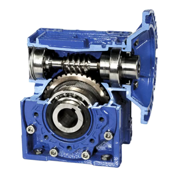
What Goes Into Every EPNMRV Gearbox
The following material specifications and construction methods apply across all 10 EPNMRV models. Individual model pages do not repeat this information.
ADC12 Aluminium Housing
All EPNMRV housings are die-cast from ADC12 aluminium alloy (equivalent to A383.0). The finned exterior geometry increases the external surface area by approximately 30% compared to a smooth-wall housing of the same internal volume, directly improving convective heat dissipation. This is critical in Australian ambient temperatures, where sump temperature must be kept below 90 degrees C to maintain lubricant viscosity. Bearing bores are CNC-machined on a single setup to guarantee coaxiality within 0.02 mm. Standard finish is RAL 5010 epoxy paint (blue).
20CrMnTi Alloy Steel Worm Shaft
The worm shaft in every EPNMRV unit is machined from 20CrMnTi alloy steel — a chromium-manganese-titanium carburising grade that provides a hard wear surface (HRC 58-62) over a tough, shock-resistant core. The carburised case depth is controlled to 0.8-1.2 mm, and every shaft is ground to a surface finish of Ra 0.8 or better after heat treatment. Worm thread lead accuracy is held within 0.005 mm. Carbon steel worms (used by low-cost competitors) lack this hardened case and wear 3-5x faster under identical load conditions.
ZCuSn10Pb1 Centrifugal-Cast Bronze Worm Wheel
Worm wheels are cast from ZCuSn10Pb1 tin-bronze (10% Sn, 1% Pb, equivalent to C93700) using centrifugal casting — not gravity or sand casting. The centrifugal process eliminates porosity, gas bubbles, and shrinkage voids that compromise fatigue life. Every pour is spectrometer-verified for alloy composition. The lead content forms a solid-lubricant reservoir at the tooth surface, reducing scoring risk during boundary lubrication conditions at start-up and at low speeds.
Seals, Lubricant & Protection
Standard seals are NBR (nitrile butadiene rubber) with Viton FKM available as an option for high-temperature or chemically aggressive environments. All EPNMRV models are sealed to IP55 as standard, with IP65 available on request. Factory fill is synthetic PAO 220 gear oil rated for continuous operation at 180 degrees C. Seal lip contact pressure and shaft surface finish are controlled to DIN 3760, targeting a minimum seal service life of 10,000 operating hours.
Efficiency, Self-Locking & Selection Guidance
This section covers the engineering principles that apply when selecting any EPNMRV model. Click each topic to expand.
Worm gear efficiency is determined primarily by the worm lead angle, which is a function of the number of thread starts and the gear ratio. Higher lead angles (more thread starts, lower ratios) produce higher efficiency. Lower lead angles (single-start worm, high ratios) produce lower efficiency but enable self-locking.
Across the EPNMRV range, typical dynamic efficiency (measured at 1,400 RPM input speed, steady state, oil temperature stabilised) follows this general pattern:
- Ratios 5:1 to 10:1 (multi-start worm): 85-90% efficiency
- Ratios 15:1 to 20:1 (double-start worm): 78-85% efficiency
- Ratios 25:1 to 30:1 (single-start worm): 65-75% efficiency
- Ratios 40:1 to 60:1 (single-start worm): 50-65% efficiency
- Ratios 80:1 to 100:1 (single-start worm): below 50% efficiency
Published efficiency values are measured under ideal conditions. Real-world efficiency is affected by running-in period (5-10% lower for the first 100-200 hours), partial-load operation, ambient temperature, and lubricant condition. For the exact efficiency values of each model at each ratio, refer to the Gear Parameters tab on the individual model page.
Self-locking is the ability of the worm gear to prevent the load from back-driving the motor when power is removed. It occurs when the friction at the worm-to-wheel contact exceeds the driving force of the load acting on the worm wheel.
Dynamic Self-Locking
Occurs when the motor is suddenly de-energised and the output must stop. The condition for dynamic self-locking is a dynamic efficiency below 0.5 (50%). In the EPNMRV range, this is reliably achieved at ratios of 40:1 and above with a single-start worm. At ratios of 25:1 to 30:1, self-locking is marginal and should not be relied upon without additional verification.
Static Self-Locking
Occurs when the gearbox is at rest and the load attempts to rotate the output shaft. The condition is a static efficiency below 0.5. Static efficiency is typically lower than dynamic efficiency, so a gearbox that self-locks dynamically will generally also self-lock statically.
Important Limitation
Self-locking should never be used as the sole safety mechanism for suspended loads or personnel-carrying applications. Vibration, shock loads, and temperature changes can temporarily reduce friction at the worm-to-wheel interface, potentially allowing the load to creep. For safety-critical applications, always install a separate holding brake or mechanical backstop in addition to worm gear self-locking.
Each EPNMRV model page contains a Selection Table showing the available combinations of input power, ratio, output speed, output torque, radial load capacity, and service factor. Follow this process to select the correct model and ratio:
Step 1: Define Your Output Requirements
Determine the required output torque (Nm) and output speed (RPM) at the driven shaft under worst-case operating conditions.
Step 2: Determine the Service Factor
Identify your load class: A (uniform, fs >= 1.0), B (moderate shock, fs >= 1.25), or C (heavy shock, fs >= 1.75). The service factor accounts for shock loading, start-stop frequency, and daily operating hours.
Step 3: Enter the Selection Table
Find a row where the output torque meets or exceeds your requirement AND the service factor (fs) meets or exceeds your load class. The corresponding input power, ratio, and model number define your selection.
Step 4: Verify Thermal Capacity
If the gearbox will run continuously in ambient temperatures above 30 degrees C, verify that the thermal power rating at your site temperature is sufficient. Contact our engineers for thermal rating verification at your specific ambient conditions.
Step 5: Confirm Mounting and Shaft Configuration
Check the Dimensions tab for housing mounting dimensions and the Output Shaft tab for shaft diameter and keyway. Verify the IEC motor flange code matches your motor. Specify the mounting orientation (B3, B6, B7, B8, V5, or V6) at time of order.
All EPNMRV gearboxes ship factory-filled with synthetic PAO 220 gear oil. For standard operating conditions (ambient temperature below 40 degrees C, continuous duty), this lubricant is suitable for the life of the gearbox with changes at 10,000-hour or 24-month intervals.
In Australian conditions where ambient temperatures regularly exceed 40 degrees C — particularly in the Pilbara, Bowen Basin, and inland New South Wales — oil change intervals should be halved (5,000 hours or 12 months). In dusty environments such as quarries and mine sites, fit a desiccant breather and monitor oil particulate count at 3-month intervals.
Do not use conventional sulphur-phosphorus EP additives formulated for steel-on-steel gears. These will chemically attack the bronze worm wheel, causing accelerated corrosive wear. Use only EP additives specifically formulated for bronze-on-steel worm gear contact.
Series Variants
- EPNMRV — Hollow input (IEC flange motor connection) + solid output shaft
- EPNRV — Solid input shaft (no flange) + solid output shaft
- EPNMRV-E — Hollow input (IEC flange) + worm shaft extending to rear (double-ended)
- EPNRV-E — Solid input + worm shaft extending to rear
Output Shaft Options
- DZ (single-side) — Standard solid output shaft, one side
- SZ (double-side) — Output shaft extending both sides of the housing
- F — Low-profile output flange
- FL — High-profile output flange
Optional Upgrades
- Viton (FKM) seals for high-temperature or chemical environments
- IP65 enhanced sealing
- FDA H1 food-grade lubricant
- Epoxy coating for corrosive atmospheres
- Torque arm for hollow-shaft mounting
Specify all options when requesting a quote.
Standard Mounting Positions
All EPNMRV models support six mounting orientations per IEC convention. Default is B3 unless otherwise specified at time of order.
B3
Horizontal foot-mount, worm above (default)
B8
Horizontal foot-mount, worm below
V5
Vertical, output shaft pointing up
B6
Vertical worm up, wall-mount
B7
Vertical worm down, wall-mount
V6
Vertical, output shaft pointing down
Non-B3 orientations may require modified oil fill levels and additional sealing to prevent lubricant starvation of upper bearings. Confirm mounting position with our engineers before ordering.